PWB Spacers
The Problem
High-value printed circuit boards (PCBs) occasionally undergo routing and are cut from their backing plates before completing Automated Optical Inspection (AOI). Once separated from the backing plates, these boards cannot be oriented in the AOI machines because the reference points for alignment are located on the backing plates themselves.
The existing solution involved using wooden Q-tips positioned on either side of alignment slats as stencils for applying epoxy resin. The manual process was neither sustainable nor scalable, prompting the need for a more efficient alternative that could be presented to upper leadership.
The Solution
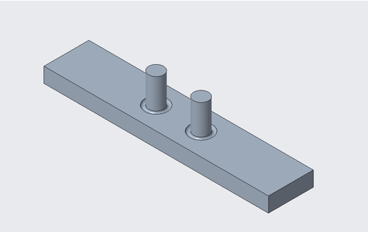
Working within the constraints of available resources and no initial project budget, I explored 3D printing as a cost-effective manufacturing approach. The design process was highly iterative, beginning with cylindrical spacers, and moving through variations of rectangular spacers. Initial prints produced out of spec results, but printing the designs inverted improved the dimensional accuracy.
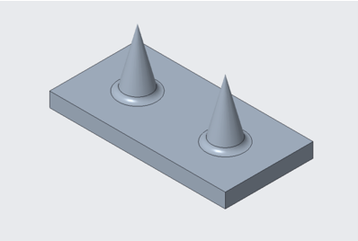
To address these limitations I developed alternative geometries including conical and cylindrical designs. The conical design printed effectively, but didn’t properly space the board. Conversely, the cylindrical prototype had issues printing in spec but showed improved compatibility with the boards.
While 3D printing proved valuable for this rapid prototyping, ongoing work includes researching commercial ESD compliant washers as a long term solution as well as continuous development for optimal spacers.
Final Design
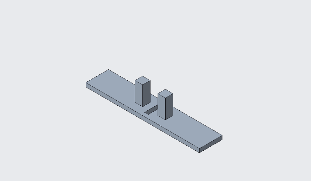
The rectangular spacers printed upside down proved to be the most effective solution. This design incorporated a slit in the base to allow flexibility, accommodating boards with varying radii by bending into the alignment slots. This printed solution is a step up from the initial Q-tip set up, and has led to more effective board throughput while developing a budgeted solution.